


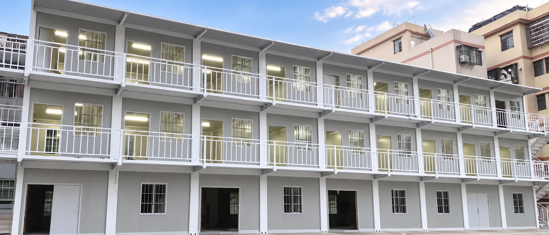
Flat-pack modular building product
Flat-Pack Container House
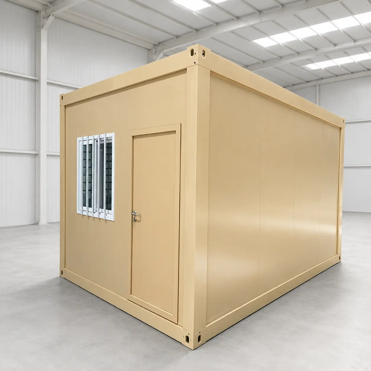
Product overview
A configurable flat‑pack system for project sites
A transport-efficient modular unit with factory-prepared roof and floor assemblies, configurable enclosure components and project-specific interior fit-out.
Complete product description
A factory-prepared building package for site assembly
The Flat-Pack Container House is a purpose-built modular building unit supplied as coordinated structural, enclosure and fit-out components.
Roof and floor assemblies are prepared before shipment; columns, wall panels, doors, windows and specified service items are packed for transport and assembled at the destination.
A unit can operate as a standalone room or connect with additional units to create larger floor plans.
Accommodation, office, dining, sanitary, laundry and other project-support functions are developed by selecting the room layout, openings, internal finish and service scope required for that building.
The product is available in different dimensional and component schedules.
The 20-foot and 3 m-wide references shown on this page are separate configurations; structural members, panel build-ups, glazing, electrical items and packing quantities are confirmed against the selected model rather than treated as universal specifications.
- Product type
- Flat-pack modular building unit
- Primary structure
- Galvanized cold-formed steel frame
- Envelope
- Insulated sandwich-panel system
- Configuration
- Single units or coordinated multi-unit layouts
- Typical functions
- Accommodation, office, dining, sanitary, laundry and support spaces
Factory package
Roof and floor assemblies, structural frame, enclosure components and approved fit-out items are coordinated for packing and shipment.
Site assembly
The package is erected on prepared foundations and connected to external utilities in accordance with the approved project scope.
Building layouts
Single units can be linked horizontally. Multi-level arrangements require project-specific engineering, access planning and local approval.
Specification control
Production follows the approved drawings, model schedule, room requirements and responsibility matrix for the project.
Supplier assurance
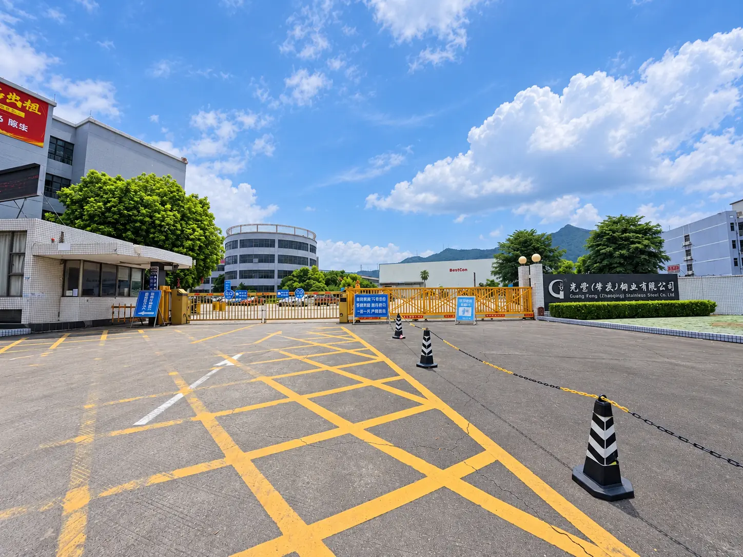
Review the capability behind the product package
The company profile documents the production environment, quality-control approach and export-support resources available to project teams. Use these records alongside the product specification and completed cases.
Model references
Keep each configuration tied to its own schedule
These values support early product selection. The final quotation, drawings and material schedule confirm the complete supply for the selected model.
| Planning item | 20-foot reference | 3 m-wide reference |
|---|---|---|
| External dimensions | 5990 × 2438 × 2896 mm | 6055 × 2990 × 2896 mm |
| Internal dimensions | Confirm against the selected 20-foot schedule | 5845 × 2780 × 2550 mm |
| Structural basis | Galvanized steel frame; member sections and thicknesses are model-specific | Q235B galvanized cold-formed steel; member thickness varies by member type and schedule |
| Envelope reference | Insulated sandwich panels; build-up confirmed by selected schedule | 100 mm wall-panel assembly with 75 mm glass-wool core for the 3 m-wide standard configuration |
| Floor reference | Cement-fibre board with PVC finish; thickness confirmed by selected schedule | 19 mm cement-fibre board for the 3 m-wide standard configuration |
| Multi-level planning | Project-engineered and subject to local approval | Up to three storeys for the 3 m-wide configuration, subject to project review and local approval |
| Logistics reference | 6 to 8 sets per 40-foot high-cube container, depending on configuration and packing plan | Confirmed after the approved material and packing schedule |
Specification control: Frame thickness, panel build-up, glazing, opening size and electrical components vary across the reviewed schedules. A value shown for one configuration must not be applied to another without written confirmation.
Model confirmation
Need a specification tied to your project?
Send the destination, intended room use, model preference and quantity. The response can then reference the applicable configuration instead of combining values from different schedules.
System components
Confirm every building layer before production
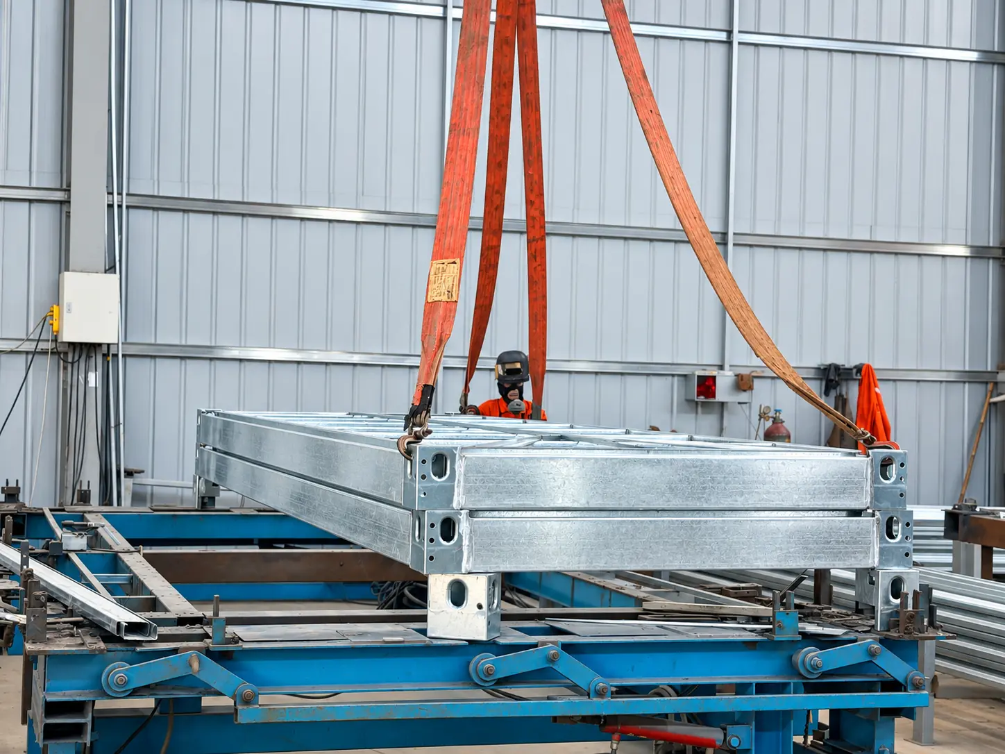
- Frame
- Galvanized cold-formed steel; member sizes and thicknesses follow the approved model schedule.
- Walls
- Insulated sandwich panels with rock-wool or glass-wool core, depending on configuration.
- Roof and drainage
- Insulated roof assembly with coordinated internal drainage; build-up is model-specific.
- Ceiling
- Profiled galvalume-coated steel ceiling panel.
- Floor
- Cement-fibre board with PVC finish; board and finish thicknesses are confirmed by model.
- Openings
- Steel door and PVC sliding window; glazing, mesh and screen follow the selected package.
- Electrical preparation
- Distribution board, lighting, sockets and air-conditioner provision coordinated to the destination requirement.
Selectable scope
Options belong to the approved product specification
Selections are recorded against the model and destination rather than presented as universal standard features.
- 01Frame selection
Member sections and thicknesses are chosen from the applicable model schedule and project design basis.
- 02Wall-panel build-up
Insulation material and thickness are confirmed for the selected configuration.
- 03Doors and windows
Opening sizes, glazing, security mesh and insect screens are coordinated with the room plan.
- 04Electrical components
CE, UL or SAA marked components can be selected where applicable. Component marks do not certify the complete building.
Layout and fit-out
Define the room function before the final product schedule
The structural unit is only one part of the finished building. Room planning, fit-out, services and site interfaces determine the complete supply.
01 / Room plan
Internal use and occupancy
Confirm each room function, furniture arrangement, sanitary requirement and the number of users. This establishes partitions, doors, windows and circulation.
02 / Envelope
Panels and openings
Select the applicable wall-panel build-up, door and window schedule, glazing and screens from the configuration available for the project.
03 / Services
Electrical and water interfaces
Coordinate lighting, sockets, air-conditioner provision and any internal water or drainage items included in the scope. Destination requirements govern electrical selection.
04 / Interior scope
Finishes, fixtures and equipment
Confirm floor finish, internal fixtures, furniture and equipment separately. Representative interiors in the product gallery are not automatic inclusions.
Information required for a complete product quotation
- Project location and destination standard
- Selected model and quantity
- Room schedule and layout
- Single- or multi-level arrangement
- Door, window and panel requirements
- Electrical, water and drainage scope
- Furniture, fixtures and equipment
- Delivery, unloading and installation responsibilities
Factory-office application
Why factories choose modular offices
Customer feedback usually centres on four practical buying reasons. The final benefit depends on the approved scope, site conditions and whole-life cost comparison.
01 / Programme
Earlier occupancy
Factory-prepared components and planned site assembly can shorten the route to usable office space once drawings, foundations, utilities, approvals and labour are ready.
02 / Layout
Multiple functions in one plan
Connected units can form offices, meeting rooms, reception, welfare and support areas. Partitions, openings and services are coordinated around the actual workflow.
03 / Change
Relocation potential
Where the selected system, unit condition and transport route allow, modules can be dismantled and reassembled for a later factory phase. Reuse requires a project-specific review.
04 / Commercial basis
Ownership instead of continuing rent
For a long-use project, purchasing may replace recurring office rent. Compare the complete delivered cost, site work, utilities, maintenance and planned service life before deciding.
Packing and site assembly
Match the factory package to the delivery and site plan
For preliminary logistics planning, the 20-foot configuration is listed at 6 to 8 sets per 40-foot high-cube container, with a reference crew of four and approximately three hours of assembly per unit under normal site conditions.
Final packing quantity and installation planning depend on the selected specification, shipment accessories, route limits, unloading method and site readiness.
- 01Confirm foundation and utility interfaces
- 02Approve packing and shipment schedule
- 03Prepare unloading and lifting access
- 04Assemble to approved drawings
- 05Connect external services
- 06Complete inspection and handover
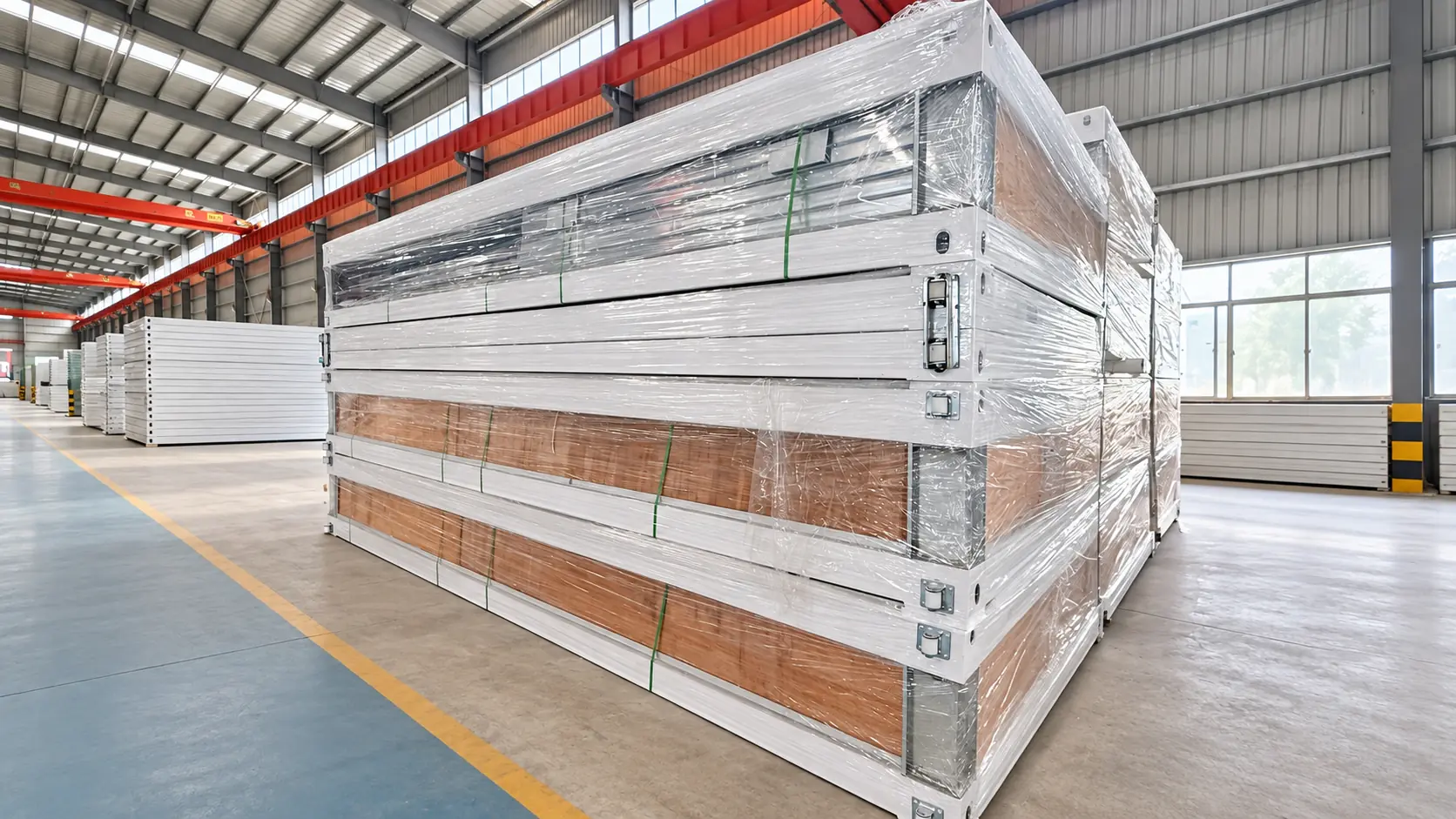
The sequence is a product overview, not a site instruction. Approved installation drawings, lifting requirements, local safety procedures and the agreed responsibility matrix govern the work.
Project references
See the product system in completed projects
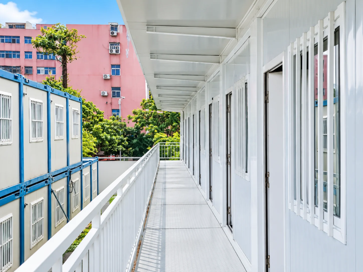
73-unit flat-pack office and accommodation project
A completed modular project combining office and accommodation functions with external circulation.
View Project278-unit Philippines PV engineering camp
A large flat-pack modular accommodation project delivered for a photovoltaic engineering workforce.
View ProjectNorthwest China mining workforce camp
Delivered flat-pack accommodation blocks with covered external circulation, shared sanitary facilities and controlled camp access.
View ProjectOil and gas modular workforce camp
A delivered flat-pack camp combining accommodation, project offices, meeting rooms, sanitation and operational support buildings.
Project enquiry
Send the information needed to define the product
Share the destination, intended use, room schedule, quantity, preferred model width, storey requirement, fit-out scope, delivery target and available site information.
The room layout, openings, insulation, electrical scope and interior fit-out can be customized around the actual project after the model and destination requirements are confirmed.
Send Project RequirementsWhich dimensions are standard?
Available references include a 5990 × 2438 × 2896 mm 20-foot configuration and a 6055 × 2990 × 2896 mm 3 m-wide configuration. Their component schedules differ, so the selected configuration must be confirmed before quotation.
Can units be combined or stacked?
Units can be linked for larger layouts. Multi-level arrangements require project-specific structural review, circulation planning and local approval. The 3 m-wide standard configuration allows planning for up to three storeys, subject to these checks.
Can electrical components match the destination?
Switches, sockets, wiring and selected components can be coordinated for destination requirements. Final component selection and electrical scope are confirmed before production.
What should be confirmed before quotation?
Provide the project location, building functions, model preference, quantity, room layout, storeys, fit-out, destination port, target delivery date and site access information.
What remains outside the factory package?
Foundations, inland delivery, unloading, lifting, site assembly, external utilities, local approvals and commissioning responsibilities must be assigned in the approved project scope.