
Prepared components
Frame members, panels, boards, openings and selected electrical items follow the approved schedule.

 English (UK)
Factory-prepared frame, roof, floor and enclosure components are packed separately, identified for shipment and assembled into complete units at the destination.
5990 × 2990 mm reference · Basic and quality schedules · Bolted site assembly
Complete product description
The Detachable Container House is a bolted modular building system supplied as coordinated structural, roof, floor, wall and opening components.
Columns, beams, panels, boards, doors, windows and selected electrical items are prepared for the approved model before shipment.
At the destination, the parts are unloaded, checked against the packing list and assembled in sequence on a prepared bearing surface.
The floor frame, columns and roof frame establish the primary structure before the enclosure, openings and selected services are installed.
The supplied schedules document basic and quality references for the same 5990 × 2990 × 2800 mm external size. Member thicknesses, sheet gauges, openings, electrical scope, finish and packing method must follow the selected order schedule.
Frame members, panels, boards, openings and selected electrical items follow the approved schedule.
Components are grouped, wrapped and identified for the confirmed container or truck loading plan.
Floor, columns, roof, enclosure and openings are installed in the approved order.
Room layout, finishes, electrical standard and external connections follow the order documents.
Supplier assurance
A detachable system depends on accurate member preparation, component identification, packing control and complete order documentation. Review those controls together with the selected product schedule.
Reference configurations
The two supplied schedules share the same reference dimensions but use different member thicknesses, sheet gauges and opening specifications.
| Specification item | Quality reference | Basic reference |
|---|---|---|
| External dimensions | 5990 × 2990 × 2800 mm | 5990 × 2990 × 2800 mm |
| Internal clear dimensions | 5820 × 2720 × 2450 mm | 5820 × 2720 × 2450 mm |
| Column reference | 210 × 150 mm galvanized cold-formed steel, 2.3 mm | 210 × 150 mm galvanized cold-formed steel, 2.0 mm |
| Floor main beam | 160 mm section, 2.3 mm | 160 mm section, 2.0 mm |
| Roof sheet | 0.426 mm profiled colour steel | 0.376 mm profiled colour steel |
| Ceiling liner | 0.326 mm profiled colour steel | 0.286 mm profiled colour steel |
| Wall panel | 50 mm rock-wool sandwich panel, 0.286 mm steel skins | 50 mm rock-wool sandwich panel, 0.276 mm nominal steel skins |
| Door reference | 840 × 2035 mm A-grade steel door | 920 × 1980 mm C-grade steel door |
| Window reference | 1130 × 1100 mm PVC sliding window, single glazing, security bars and screen | 950 × 1100 mm PVC window, single glazing and security bars, without screen |
Specification control: The selected schedule, approved drawings and signed quotation define the final model. Do not combine values from the basic and quality references unless the variation is recorded in the order documents.
Model confirmation
Send the location, room use, quantity, electrical standard, site access and target delivery date so the quotation can identify the applicable configuration.
System components
The reference schedules identify the component build-up below. Gauge, opening and electrical selections remain tied to the approved basic or quality configuration.
Configuration control
The order should connect every variation to the model, room function, destination and assigned responsibility.
Select the basic or quality frame and enclosure basis before individual variations are priced.
State occupancy, furniture, internal zoning, openings and circulation requirements.
Record voltage, socket standard, utility interfaces and any plumbing or sanitary scope.
Coordinate component labels, container plan, unloading access, tools, crew and target programme.
Packing and assembly
A component-built system relies on correct identification, protected unloading and disciplined assembly. The approved drawings and method statement govern the work.
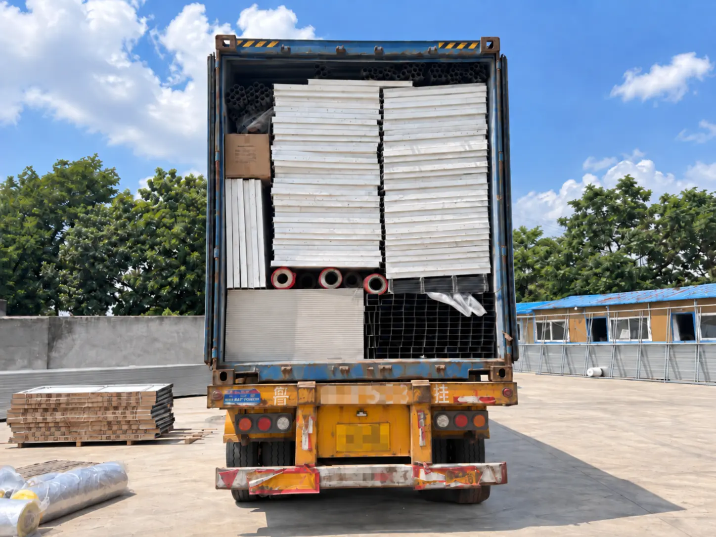
Site responsibility: Bearing surfaces, local permits, unloading access, temporary storage, assembly tools, external utilities, testing and commissioning must be assigned in the project responsibility matrix.
Project applications
Suitability depends on occupancy, local approval, climate, service demand, access and the approved configuration.
Repeatable sleeping or welfare rooms planned around occupancy and utility demand.
Temporary project buildings where component transport and staged assembly suit the site plan.
Single or connected rooms with destination-specific openings, finishes and electrical scope.
Support spaces coordinated with restricted access, storage, assembly and utility conditions.
Project enquiry
Share the destination, intended use, quantity, required utilities, access conditions and target date. The response can then define the schedule, supply scope, packing plan and assembly responsibilities.
Start a Project EnquiryThe approved schedule defines the structural frame, roof and floor components, wall panels, openings, fasteners and selected electrical items. Packing lists and quotation documents control the final supply.
The quality reference uses thicker columns and floor main beams, higher roof and ceiling sheet gauges, a different wall-panel profile and upgraded opening specifications.
The system is delivered as separate components rather than a completed volumetric unit. The required lifting aids, unloading method and assembly equipment depend on the approved method statement and site conditions.
Units can be coordinated into connected layouts when structural interfaces, weather sealing, circulation, utilities and local approval are addressed in the project drawings.